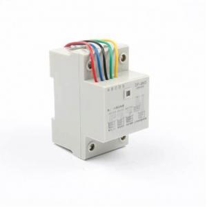
DF-96D Automatic Water Level Controller Switch 10A 220V Tank Liquid Level Pump Controller
Introduction
This product uses integrated circuit, and combines the high-rise building. The water level of the lower pool (water tower) is designed by grade lifting. It has the functions of joint control of the upper and lower pools, water drainage and water shortage protection. It can automatically realize water refill and drainage of the water tank, and effectively prevent the overflow of the water level of the pool or the damage of the pump idling
Specification
model | DF-96D |
Dimensions | 126×88×74mm |
Operating Voltage | 220V |
Installation method | guide |
Power consumption | ≤2W |
load | 10A |
Installation
Single-control UP pool (water storage) installation instructions shown in figure 1

A(red)—Upper water level control point. When water level gets to A point,
the probe touch water and controller can stop the pump by auto.
B(blue)—Lower water level control point. When water level gets off B point,
the probe out of reach water and controller can start the pump by auto.
C(black)—Should be placed in bottom of pool as the common line.
D(green) and E(yellow)are connected with C (black).
Single-control DOWN pool(drain water)installation instructions shown in figure 2.

E—Upper water level control point. When water level gets to E point,
the probe touch water and controller can start the pump by auto.
D—Lower water level control point. As liquid level gets off D point,
the probe out of reach water and controller can stop the pump by auto.
C—Should be placed in bottom of pool as the common line.
A&B—disconnected
1 . Lack of water protection installation instructions shown in figure 3.

C&D—Lower water level control points. When water level gets off this point,
C or D probe out of reach water and controller can stop the pump by auto.
E&C—short-connected;
A&B—disconnected
2 . Joint control UP and DOWN pool installation instructions shown in figure 4.

A—Upper water level control point in UP pool. When water level gets to A point,the probe touch water and controller can stop the pump by auto.
B—Lower water level control point in UP pool. When water level gets off A point, the probe out of reach water and controller can start the pump by auto.
C—Should be placed in bottom of UP and DOWN pools as the common line.
D—Lower water level control point in DOWN pool. When water level gets off D point, the probe out of reach and controller can stop the pump by auto.
E—Upper water level control point in DOWN pool. When water level gets to E point, the probe reach water and controller can start the pump by auto. Then pool starts to drain water. If not, E point disconnected
Performance characteristic
Used to solve problem:
1. On power but no work:
a. Check the red indicator is on or not. If not, make the connection is good enough;
2. When water level is above or below probes but the pump does not start or stop by auto, Please check it like the following.
a. Whether the probe is placed too high or low so that water level can reach or out of reach it;
b. The connection of upper &lower line or probe is dislocation by error or short connected;
c. To check the probe whether it is rust or not or the connection is good enough.
d. C- Check the common line whether it is placed in the lowermost bottom of pool.

220V


Market application
It is very suitable for urban and rural schools, industrial and mining enterprises and institutions as well as the water tower well water supply project.
- printing and dyeing
- chemical industry
- food and beverage
- brewing sugar
- other industries
